

MOV vs SMD Varistor Selection Guide for Surge & ESD Protection
Suntan Technology Company Limited
· All Kinds of Capacitors
SMD varistors are optimized for high-speed interface ESD protection where capacitance, placement distance, and return path inductance determine signal integrity. Proper device selection at USB, Ethernet, and RF connectors prevents IEC 61000-4-2 failures without degrading eye diagram margin or differential impedance.
Low-capacitance ESD protection placed at the connector with direct ground return path
High-speed communication ports fail ESD testing not because of insufficient clamping voltage, but due to excessive capacitance and long current return paths. Field symptoms typically include USB re-enumeration, Ethernet link drop, or RF desense without permanent damage, indicating transient coupling into the PHY or transceiver domain.
Failure Mode in High-Speed Interfaces
IEC 61000-4-2 contact discharge introduces sub-nanosecond rise time and peak current above 30 A. When protection devices are located more than a few millimeters from the connector, parasitic inductance generates overshoot voltage that exceeds transceiver tolerance. Excess device capacitance further distorts differential impedance.
ESD Current Path and Ground Return
Effective ESD protection requires a direct, low-inductance path from the connector shell to ground. The protection device must be placed within 5 mm of the entry point, with a wide ground via array to minimize loop inductance. Long traces increase L·di/dt voltage and negate clamping performance.
Capacitance Impact on Signal Integrity
Protection capacitance loads the differential pair and alters impedance matching. 100 pF class devices cause eye diagram closure and increased insertion loss. Sub-5 pF SMD varistors maintain return loss and preserve high-frequency content in USB 2.0, Ethernet, and RF modules.
| Capacitance | Impact on Interface |
|---|---|
| 100 pF | Eye diagram degradation and impedance mismatch |
| 20 pF | Marginal for high-speed differential pairs |
| <5 pF | Maintains signal integrity and low insertion loss |
Placement Distance and Inductance Effect
Each millimeter of trace length adds parasitic inductance that increases peak voltage during ESD. Protection devices must be located at the connector entry with the shortest possible ground return. Distributed ground vias reduce current crowding and improve clamping efficiency.
SMD Varistor vs TVS in Data Lines
SMD varistors provide symmetrical bidirectional protection with low capacitance and robust ESD handling. TVS diodes offer lower clamping voltage but typically introduce higher capacitance in standard packages. Device selection depends on allowable loading, bandwidth, and voltage tolerance of the interface.
Layout Rules for Connector Protection
Place the protection device at the connector pad. Route to ground using the shortest path. Use multiple ground vias adjacent to the device. Avoid stubs on differential pairs. Maintain controlled impedance routing after the protection point.
Eye Diagram Degradation Case Study
Replacing a 100 pF protection device with a 3 pF SMD varistor restores eye height and reduces jitter in USB high-speed testing. ESD performance remains compliant while insertion loss improves across the operating bandwidth.
Selection Checklist for High-Speed Ports
Maximum allowable capacitance for the interface Working voltage of the signal line ESD test level requirement Package size and placement distance Ground via density Bandwidth of the communication channel
Conclusion
High-speed interface protection is governed by capacitance, placement, and return path inductance rather than surge energy. Low-capacitance SMD varistors located at the connector preserve signal integrity while providing IEC 61000-4-2 compliance for USB, Ethernet, and RF applications.
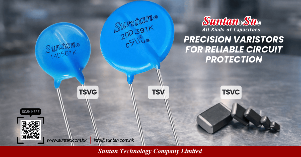
Suntan Varistor Product Catalog
MOV and multilayer chip varistor portfolio for surge and ESD protection design.
Download Varistor CatalogFor power-line surge protection and MOV energy sizing, refer to the dedicated MOV design article.
Suntan Technology – All Kinds of Capacitors.
We don’t just offer specifications — we deliver confidence for your design and sourcing decisions.